Quick start guide
Welcome to ID-10 BEATS. Below is a coarse overview of the most important steps to setup and perform your first scan. To keep to page simple but provide all information needed, links to in depth descriptions are provided in the corresponding sections.
Note
The beamline is setup for your experiment at the start of the beamtime together with the beamline staff. This includes energy adjustment and mounting detector and optics. Most of the times, there will be little to change from one scan to the next, besides aligning the sample. Ask the beamline staff before changing any beamline setting.
Getting started
The beamline control GUI allows to control the in-vacuum instrumentation in the beamline front-end, optics hutch, and experimental hutch.
Here are things users should be comfortable doing during their experiments.
In particular, you might need to adjust the configuration of:
One or more of the beamline slits
Attenuator system
search the hutch and open the shutters
adjust the sample on the stage
start a scan
The heartpiece of beamline operation is the beats-qt GUI.

Figure 1: BEATS beamline control GUI.
If it’s not already started or gets closed accidentally, it can be started from a linux console on the control computer (e.g. by pressing ctrl + alt + t) and typing
$ beats-qt
The BEATS beamline GUI allows to #. display the machine status and parameters. #. launch the BEATS Beamline vacuum GUI. The vacuum GUI is used to open the shutters of the beamline. #. launch the BEATS Experimental GUI. This GUI controls the sample manipulator and detection systems.
Beamline vacuum GUI
To be able to acquire meaningful data, you need to have X-rays on your sample. Therefore, the shutters need to be opened at least. Open the shutters only when needed and you want to measure (also to protect your sample). Openening the shutters can only be performed after the hutch has been searched.

Figure 1: BEATS vacuum GUI.
- To open the beamline light path, the shutters must be opened in the following order:
Radiation shutter.
Photon shutter.
Combined stopper.
Note
It is only allowed to open the beamline shutters once the hutches have been searched. You will see a red button besides one of the shutter if opening is not allowed.
Warning
Before opening the beamline shutters for the first time, verify with your local contact the setup of the beamline (slits, attenuator, …).
Search the hutch
Start streaming data
To access the BEATS Dashboard, type the following command:
$ BEATS_DAQ_Control_Monitor
the main GUI will appear:

Figure 1: BEATS Dashboard main window
For a very detailed description of the procedure go to BEATS Dashboard!
Set up your experiment
Note
The endstation is aligned by the beamline staff at the start of your beamtime. Generally, you don’t need to repeat these operation and you can jump to sample alignment
Warning
Collision danger: Only perform this operation together with the beamline staff. You must always pay attention to the position of endstation, detectors and sample, while performing the alignment. Always move small steps when endstation and detector are close to each other!
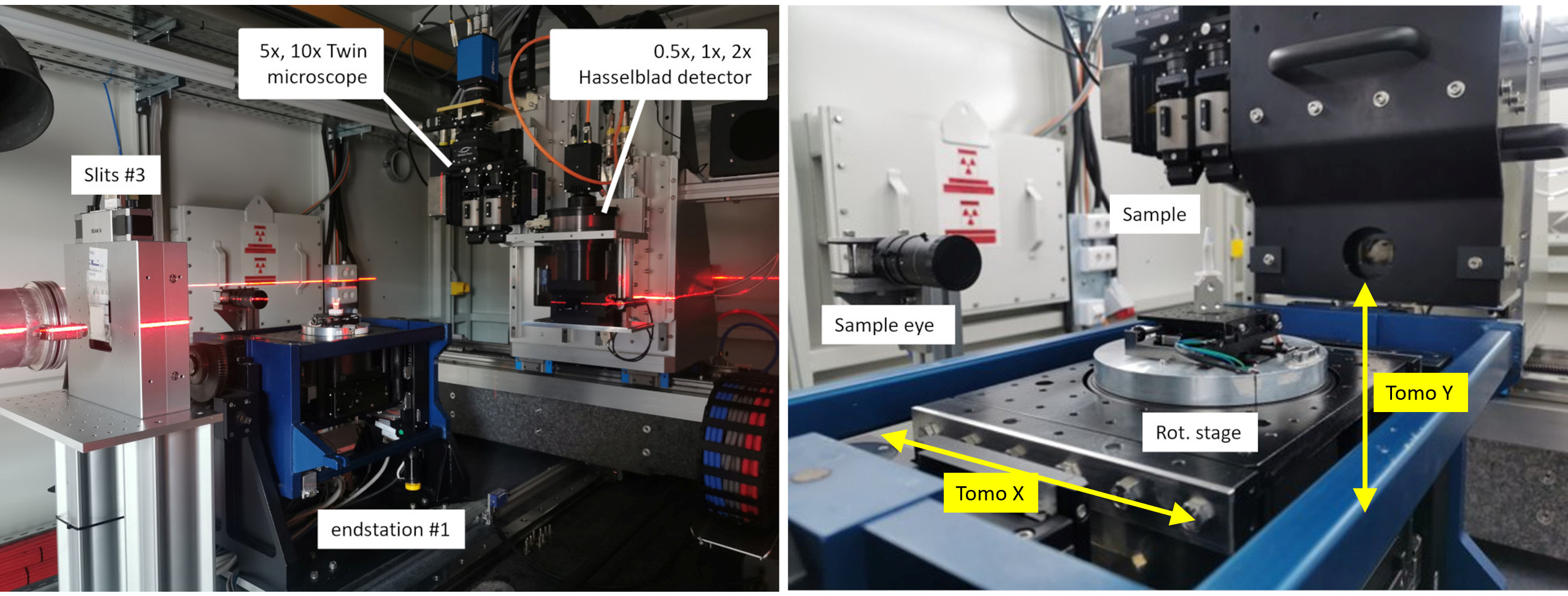
Figure 1: BEATS experimental station. Two laser lines are used to pre-align sample and detector on the beam.
Preliminary steps
Mount your sample on top of the tomography endstation (Figure 1 RIGHT)
Turn on the alignment lasers
Use the laptop close to the endstation to:
Pre-align sample on the intersection of the laser planes (you can verify this also moving the ROT stage)
Pre-align the detector scintillator on the same line
Set the distance between sample and detector to the desired value
Sample mount
Samples can be mounted on the tomography rotation stage with M4 screws as shown Figure 2.
A set of standard kinematic mounts from Newport is also available: M-BK-1A (download -> drawing).

Figure 2: (LEFT) Detail of sample tomography stage. (RIGHT) The sample plate has 9 M4 holes that can be used for custom sample support.
Sample alignment
Sample alignment procedure
Load the sample on the kinematic mount (for automatic alignemt of the endstation with Tomoalign use the tungsten wire available at the beamline as sample) then:
Perform the hutch_search
Open the shutters using the vacuum
Use the Experimental GUI to move the sample up/down until the sample is in the field of view of detector.
Experimental GUI

Figure 3: BEATS experimental GUI.